wifi biquad and card
I made a biquad antenna for 2.4GHz 802.11 and adapted a wireless card to fit it.
biquad antenna
The antenna is made of a a sheet of copper flashing cut to a 120mm square, a brass ferrule, some 10AWG magnet wire bent to form two diamonds, and a segment of RG316/U coaxial cable terminated with a female SMA connector. The flashing and ferrule are from Home Depot; the magnet wire and coax pigtail were random scraps laying around.
The biquad is a standard design based on this design. That page has a good description of how to build one, so I won't go into much detail here. The major difference was that I used a copper sheet while that design uses a copper-clad PCB; I recommend the PCB as it is much easier to solder to.
wireless card
Once I had built the antenna, though, I needed a card to drive it. Most cards do not have an antenna output and no commercial ones that I know of have one with a SMA connector to match my antenna, preferring RP-SMA instead. It's hypothesized that this is to prevent hobbyists from using the more readily available SMA connector to interface with the card. This is some complete BS, so I attached an SMA antenna output to a card that didn't have one.
I should note that I am almost certainly not the first to think of doing what I did, but I have found limited information about it elsewhere and decided that no reputable organization would describe a hack as ugly as this. Lu Laboratories is clearly no such organization.
how (not?) to do it
To start, locate the antenna feeds on your wireless card. Typically these are oddly-shaped traces at the far end of the PCB, or a nondescript surface mount block. Sometimes the feed has a small connector (typically U.FL) soldered to it. Desoldering this will give you a suitable attachment point. If not, you can scrape the solder mask off the trace feeding the antenna and use that. Be careful not to cut the trace when doing this. I used a Dremel with a buffing wheel.
You will need a suitable connector, SMA in my case. I used a PCB edge mount SMA connector, which could attach to the card with a decent press fit by clamping the pins around the board and case. I soldered a piece of thin coax (the same as used in the pigtail) between the connector and the attachment point I created, taking care to make the connections solid and not short anything. The connector and bit of coax were affixed and protected with liberal application of hot glue. This added too much thickness to fit in the case, so a hole was cut in the top cover.
testing
Testing was pretty simple. I inserted the wifi card and attached the biquad; immediately I detected many access points that were not seen in earlier wifi sniffing sessions. Rotating the antenna changed the selection of visible APs; the biquad is a directional antenna, although less so than a cantenna.
Note that while some people claim a 14dB gain from the biquad, you will likely not see such an improvement, as the connector attachment is pretty dubious and the rest of the system may be lossy as well. I am not an RF engineer, and I did not check for proper impedance matching and the like. I did notice that the wireless card became very hot after prolonged use; I am not sure if this is normal for this card, but it may indicate substantial reflected power from a poor impedance match somewhere in the connection.
Nonetheless, you should see a substantial gain in signal quality while the 'beam' is still large enough to detect lots of APs, near and far. The biquad is a good compromise between the high directionality of a cantenna and the low gain of omnidirectionals.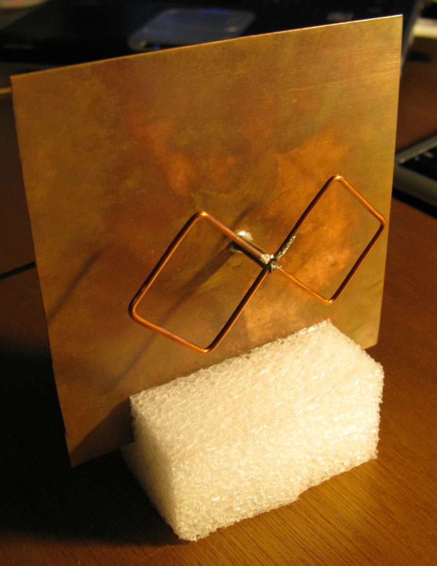 |
Here is the antenna. I cut a slot in a piece of foam for a temporary base. |
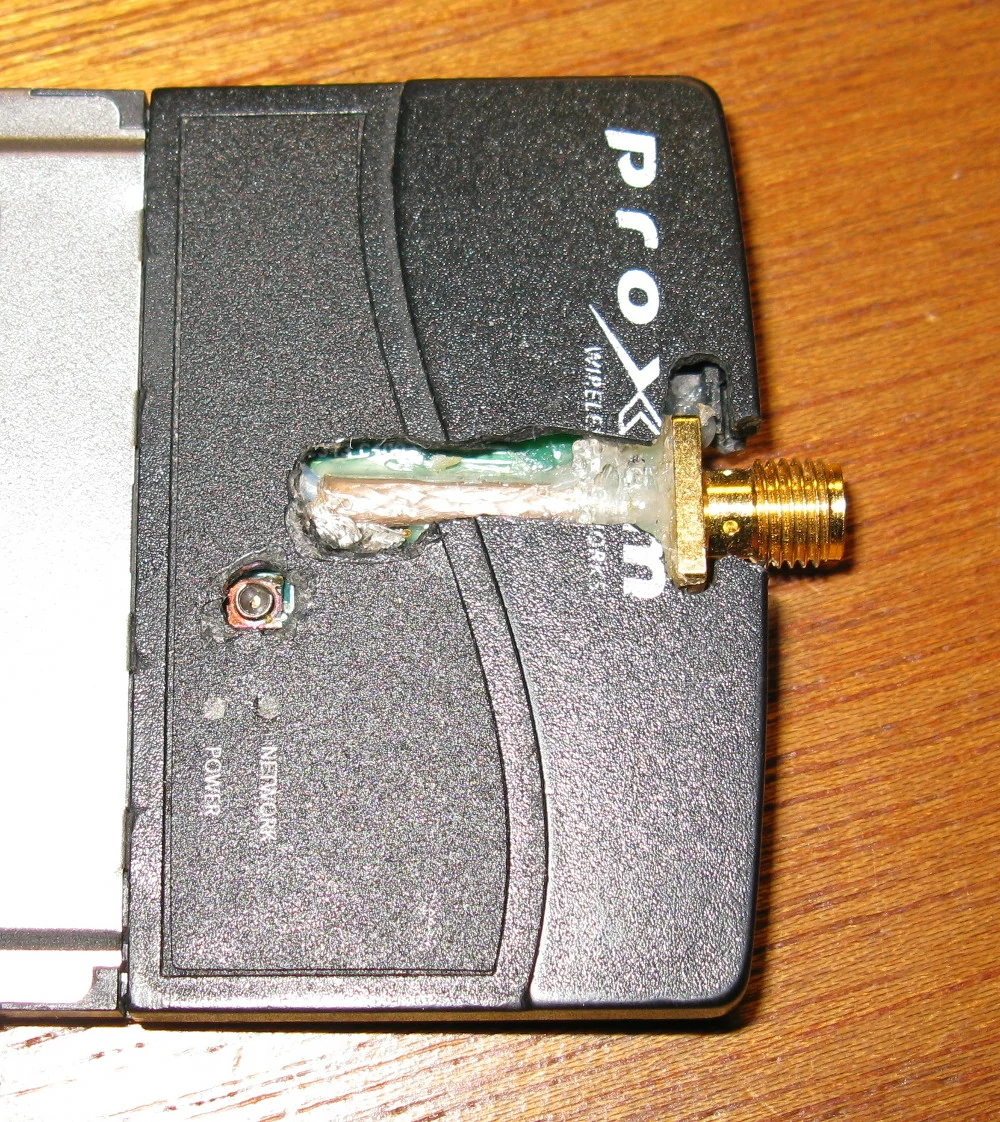 |
This is the top of the wireless card. As you can see, it is not a very clean hack. |
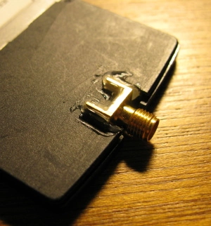 |
Here is the bottom, showing a bit more of how the SMA connector attaches to the card. |