stainless steel rubik's cube
I wasn't entirely satisfied with the aluminum cube, so after thinking about the design for a while, I decided to make another one out of stainless steel. Just for fun, I thought I would make all the pieces using only manual machines. How hard could it be?
As it turns out, it was quite a bit of type 2 fun. It sure was slow and repetitive work, but I'm pleased with the result. I was motivated to think about ways to be more efficient, like machining multiple pieces at once and using looser tolerances where allowable. The slow pace also allowed me to consider details of the design while making parts. I have never been a fan of taking things slowly, but this could be a good argument for it.
design
I started by drawing all the pieces from my knowledge of how Rubik's cube internals work. The injection molded plastic pieces in commercial cubes are not the most accurate and have looser tolerances than would be best for a machined metal one. Because the aluminum cube was produced from measurements of a plastic cube, it did not have very good fit and finish. With the amount of work that would go into this cube, I wanted it to be of high quality.
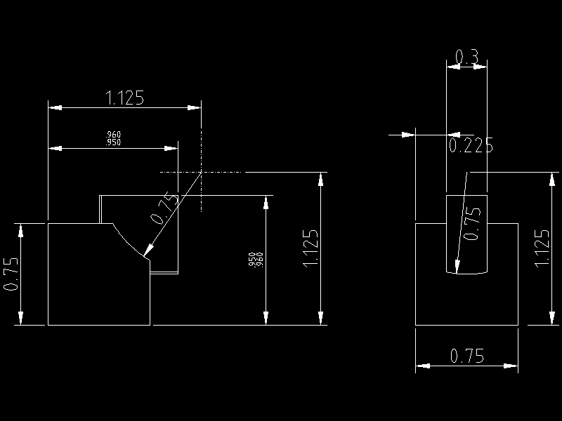
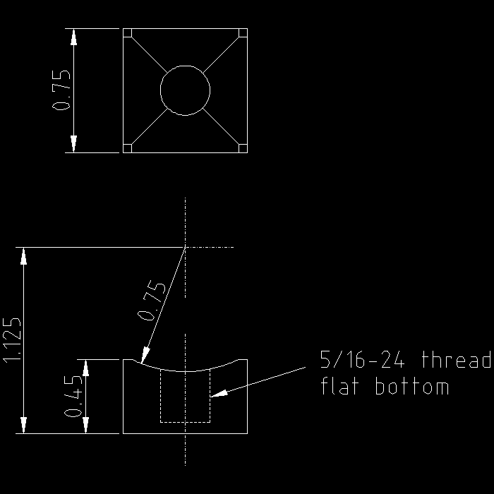
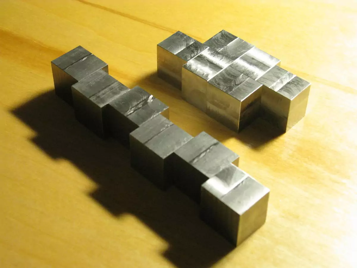
Dimensions were based on a small cube size of 0.75" (1.9 cm). All internal cylindrical sliding surfaces have a radius of 0.75" as well. Here are the exterior pieces:
Many of the interior flat surfaces do not contact each other at all, hence the loose tolerances. I tried to hold all of the unspecified tolerances to within 0.002", to avoid loose pieces as the cube is turned. The curved bottoms of the face centers allow the cube to turn more smoothly than the flat bottoms of the aluminum one did.
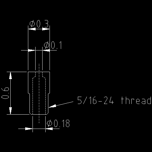
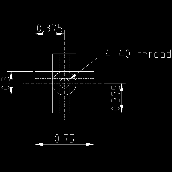
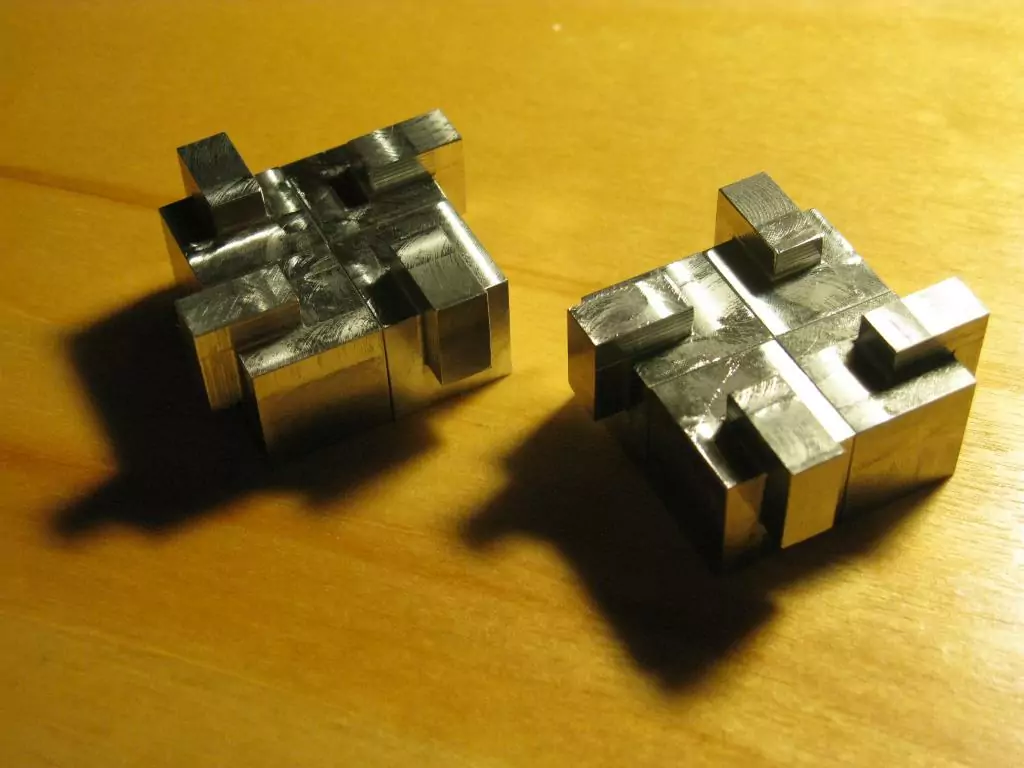
The face centers each receive a hollow stem that screws into the 5/16-24 thread. This assembly holds a captive spring-loaded screw, which screws into the core. The spring provides some give to the entire unit and allows the cube to be assembled and disassembled easily by snapping pieces in. These are the interior pieces:
The dimensions here generally have looser tolerances as there are no sliding surfaces. The stem just has to be approximately the right diameter for the 5/16-24 thread. The arms of the core have to be small enough to clear the inside bits of the pieces rotating around them - they don't even need to be round, but it was convenient to make.
fabrication
The cube is made out of 303 stainless steel. Initially I wanted to make it out of one of the more corrosion resistant austenitic alloys, like 304 or 316. However, after having tried to make other things out of frustratingly tough and gummy 304, I was defeated. 316 is no better, so I settled on the sulfurized, more machinable 303 - it's no 6061 aluminum, but at least it's not the devil's chewing gum.
As stated previously, I would try to make all the pieces on manual machines, only using CNC for the final decorative engraving. The flat faces are all quite easy to make on a manual mill with a DRO. For the curved surfaces, I initially considered using a rotary table on a mill, but then decided to use a lathe with some special fixturing for reasons explained later.
corners
edges
faces and stems
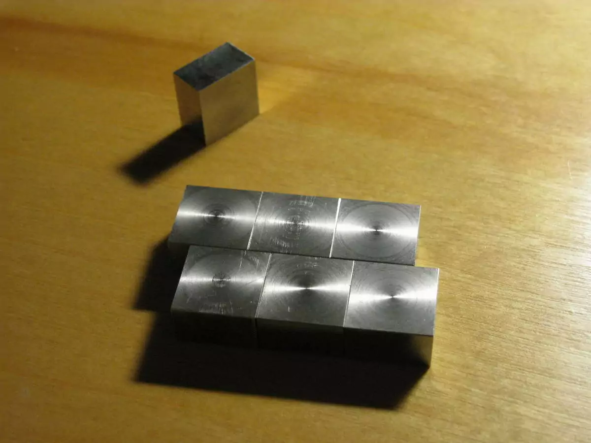 |
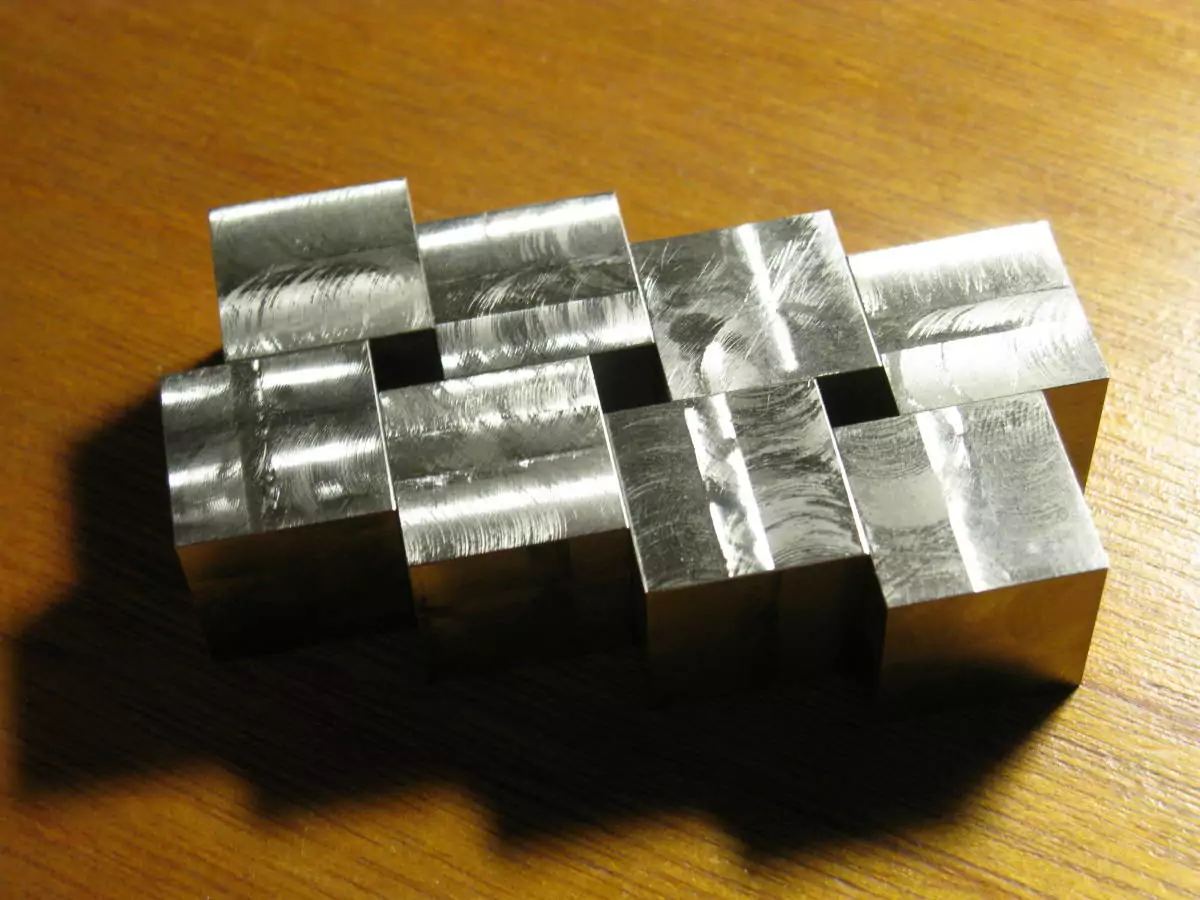
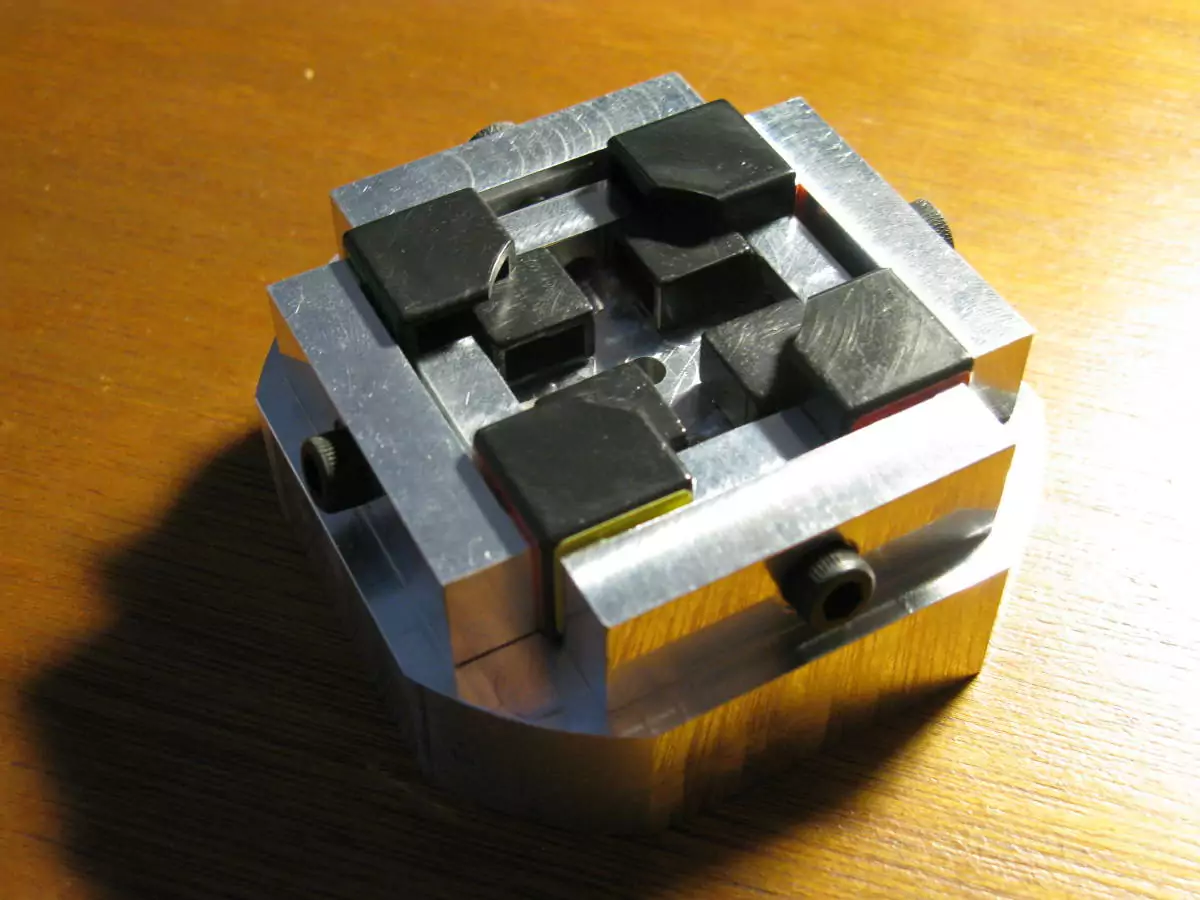
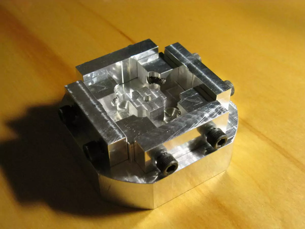
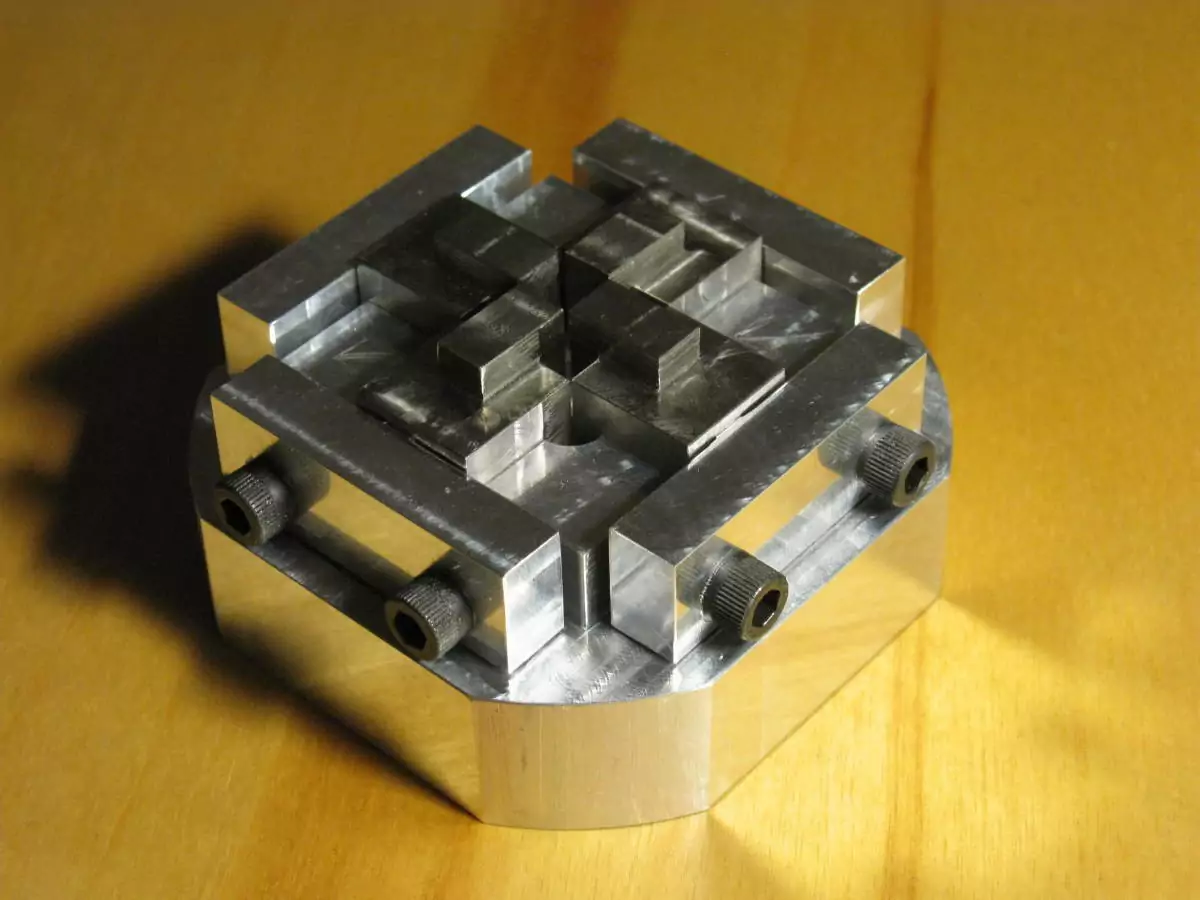
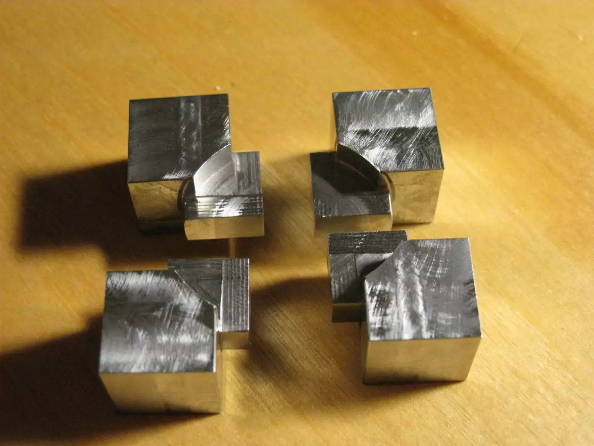
The faces start off as 0.75" x 0.75" x 0.45" blocks. I initially wanted to have a circular brushed finish on each face, so I faced the blocks on a lathe with significant extra effort. I then realized that I couldn't easily apply the same finish to the surrounding pieces. Oops. The lonely block at the top was out of tolerance. Double oops. |
 |
I began by roughing the curved bearing surfaces on the underside of each face with a 1.5" diameter roughing endmill, only to discover that roughing endmills don't have a very precise diameter. Triple oops. Fortunately, only three pieces were unusable and the other three survived with some cleanup. When I made replacements for the three scrapped pieces, I didn't take any chances and used a boring head to cut the curved bits. |
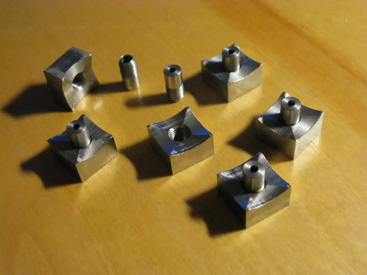 |
The next few steps are to drill and mill a 9/32" flat-bottomed hole, chamfer it, and tap it with a 5/16-24 bottoming tap. The flat bottom lets the stem seat squarely on the bottom of the hole, and the heavy chamfer on the stems clears the partial threads left from the tap. |
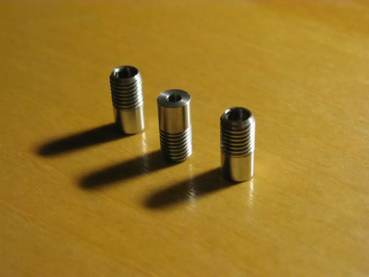 |
The stems are made from 3/8" round bar. Single-pointing the threads on a lathe seemed like a hassle and I did not have a threading tool handy, so I used a die instead. Unfortunately the dies at TechShop were the cheapest possible junk and refused to start threads. After significant frustration, I bought a proper die from a local tool shop. It started and cut a perfect thread with no difficulty at all on the first try. Good tools cost more, but they're worth it. |
core
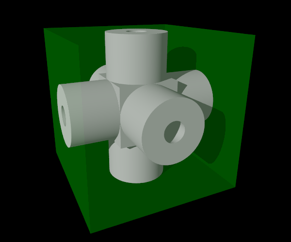
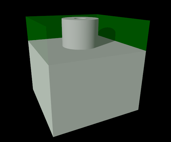
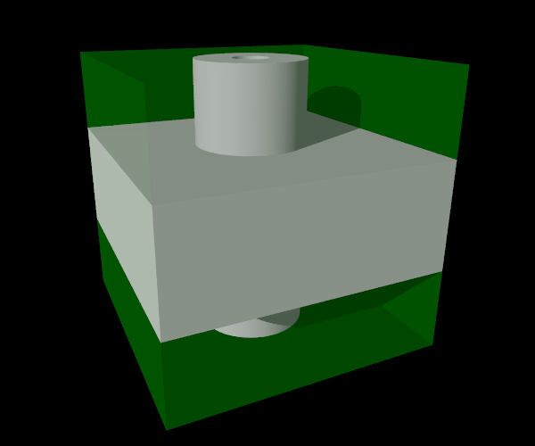
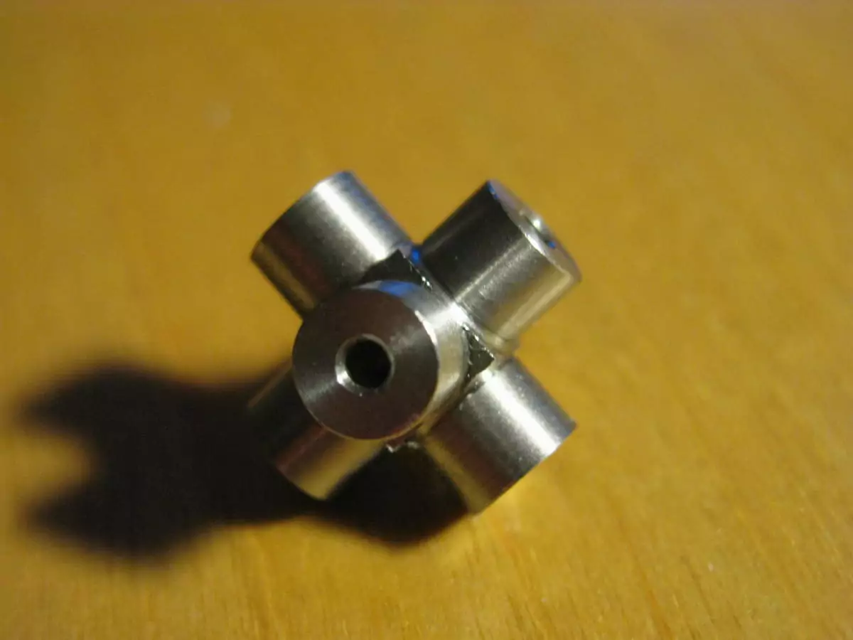
I only have a photo of the completed piece, so here are some 3D renders to illustrate the process. The entire piece is made on a lathe, using a 4-jaw chuck. From a piece of stock cut from 1" square bar, it is first turned into a 0.75" cube. Then the stock is rotated several times to turn each of the six arms.
finishing
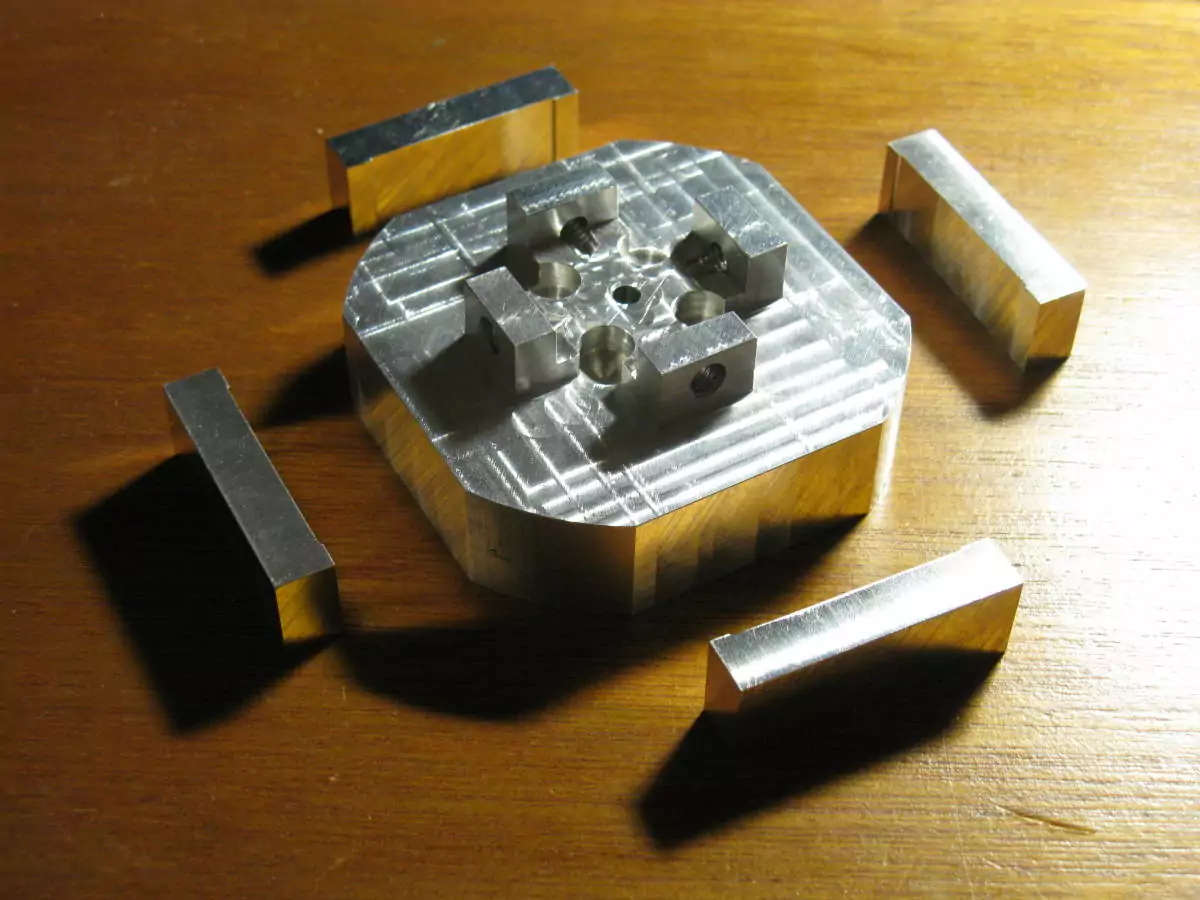
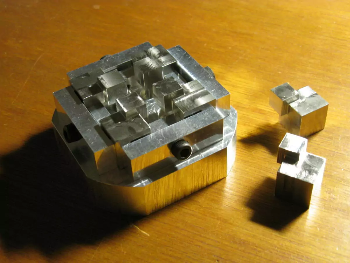
The parts are mostly complete, but the corners are too sharp for comfort and the faces aren't presentable yet. Time for finish work.
finished cube
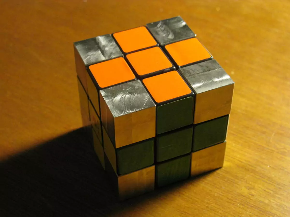
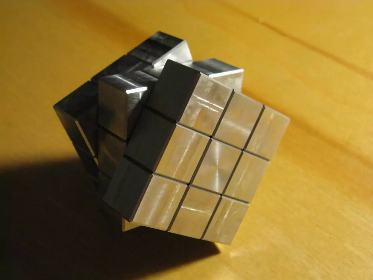
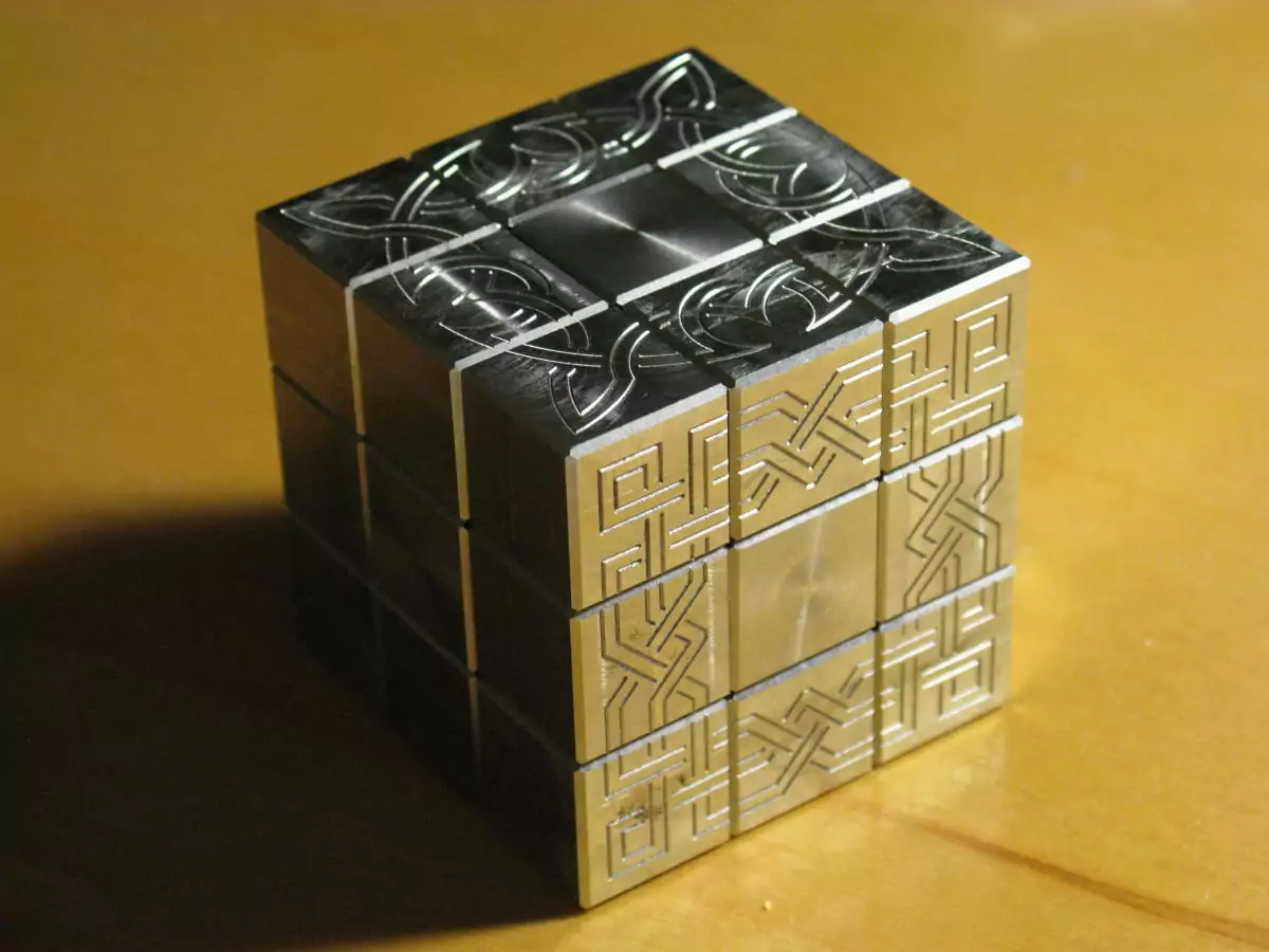
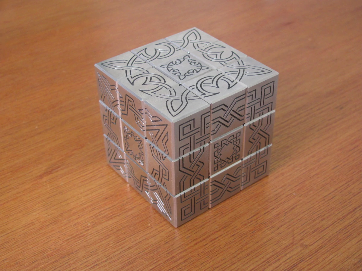
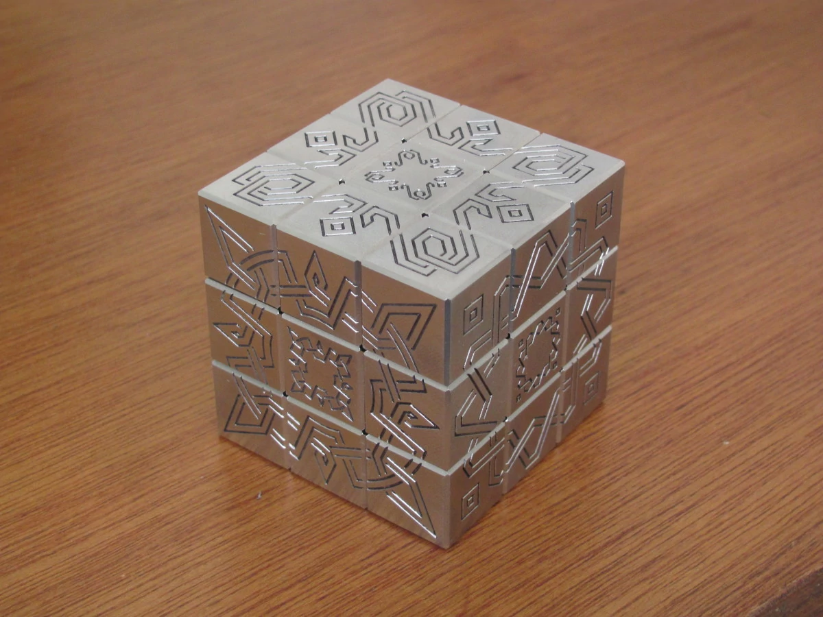
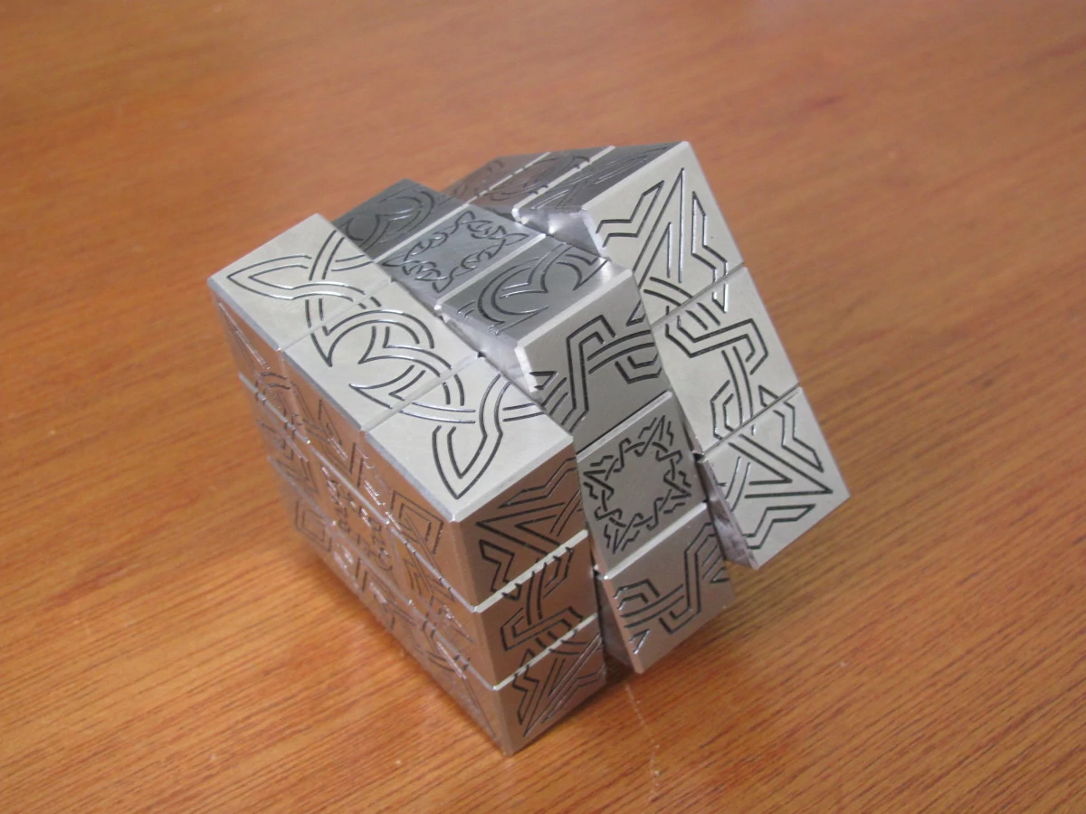
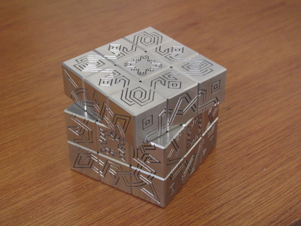
The final result is one incredibly heavy solid stainless Rubik's cube. Although it may be neat to look at, it weighs a massive three pounds (~1.4 kg) and is very tiring to manipulate. Solving this is more a test of the wrists than of the mind!
Between the relief grooves, the contours under the face centers, and the closer tolerances, this cube is much neater and smoother than the aluminum one. All the corner and edge pieces fit snugly without significant play. That does mean the faces must be better aligned to turn, but nobody would try speed cubing with this anyway.

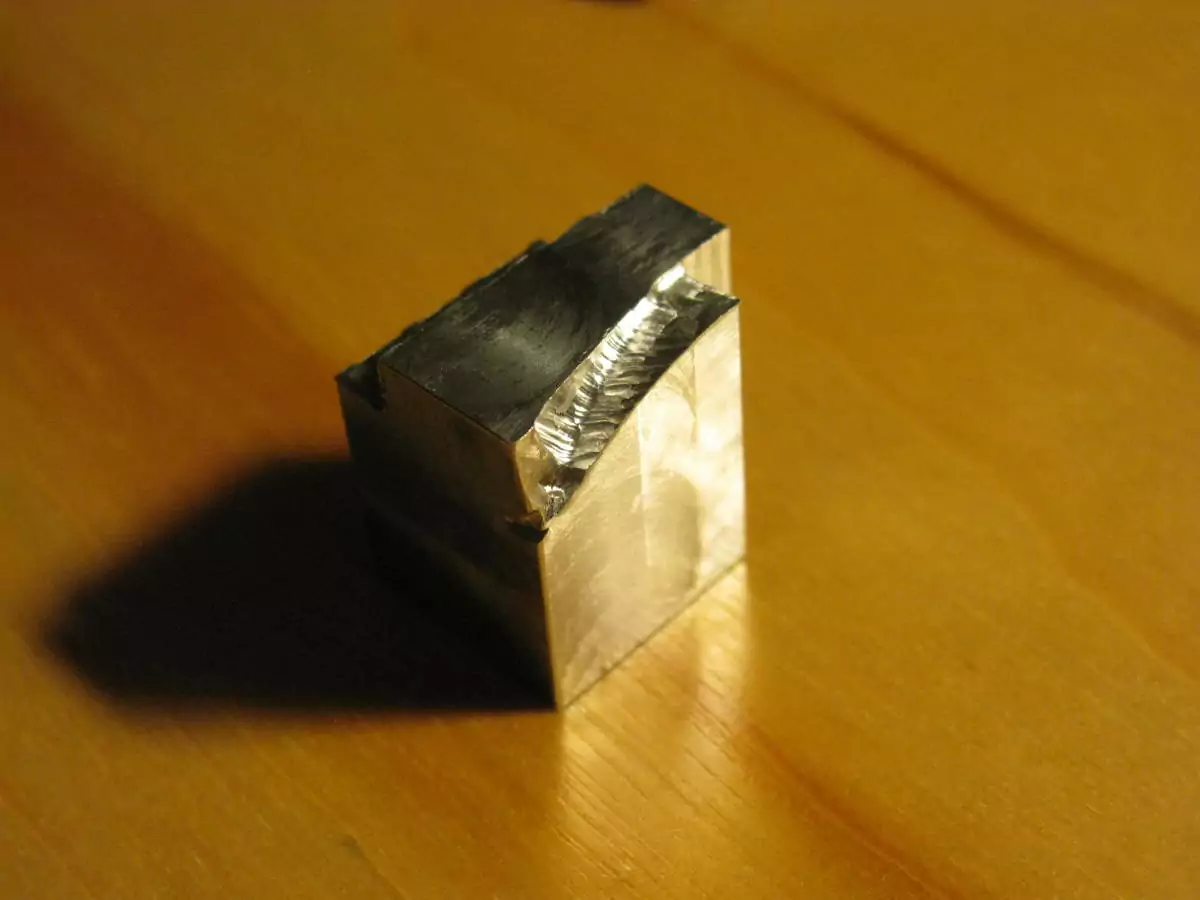
 corner piece