PLL SSTC testbed
In pursuit of the ideal SSTC, Joshua Wise, Jacob Potter, and I built this SSTC testbed in 2012. Its goal is to eventually be the One True SSTC design: scalable, robust, and flexible while being as simple as possible. We decided early on that a phase-locked loop would make an ideal oscillator. A PLL adjusts itself to feedback from the secondary, providing a stable signal to start and in theory locking the primary drive to the resonant frequency of the secondary as it changes during operation. (In practice, other things happen.)
As audio modulation is quite popular in SSTCs these days, we wanted a way to accomplish this. The typical methods of interrupting the primary drive at a set frequency and modulating the duty cycle of the drive signal would not achieve everything we wanted, so we plan to modulate the rails of the primary drive. This requires a powerful DC supply, so we used a PFC controller to build a high-efficiency supply. Rail modulation also lets us experiment with different pulse shapes, to potentially obtain different types of streamers like the straight lancing sparks of a vacuum tube coil.
Currently, the coil sits unused in Joshua's house and my attention has turned to SSTC 3.
Credit goes to Joshua for the beautiful photos of the construction process.
H-bridge driver
The primary is driven by a full bridge of four FCA36N60NF MOSFETs from Fairchild Semiconductor. Driving those are two 1:1:1 gate drive transformers, each fed from a push-pull pair of UCC3732{1,2} 9A gate drivers from Texas Instruments. Each relatively fragile MOSFET is protected by a series reverse blocking diode, an anti-parallel bypass diode, and a 15V transient suppressor between gate and drain.
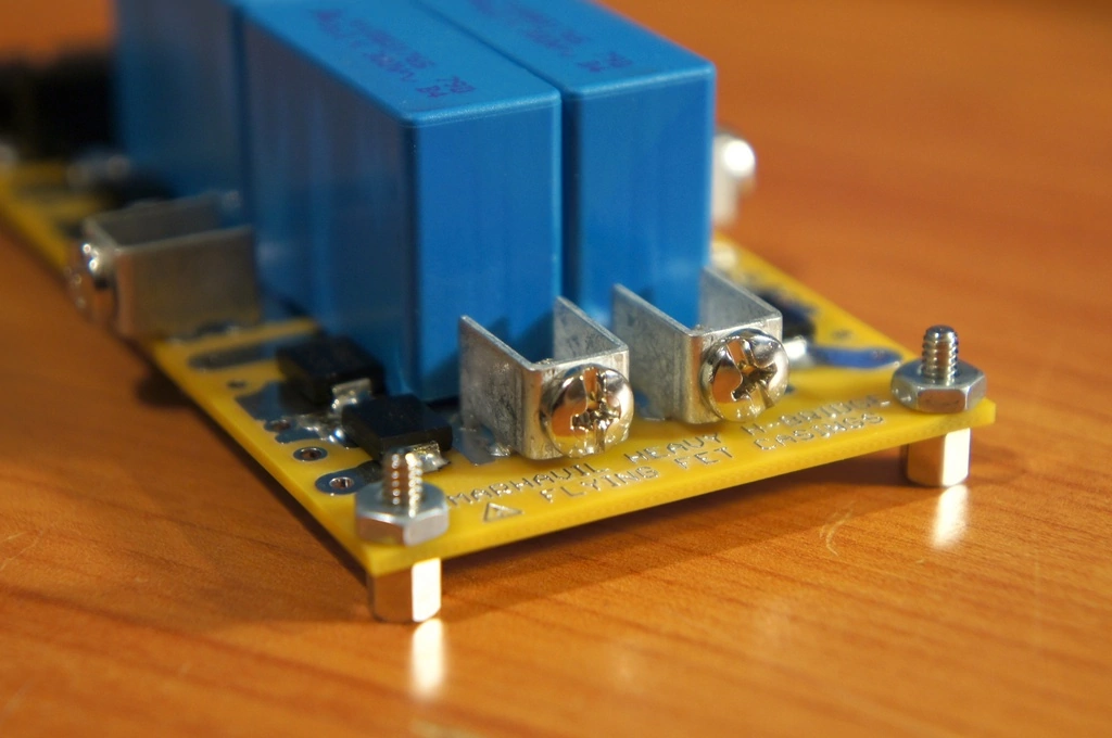 |
The board before the MOSFETs and reverse blocking diodes are attached. The surface mount diodes near the FET holes are the gate TVS and the reverse bypass diode. This board definitely lived up to its warning of flying FET casings... |
 |
The completed driver circuit. The board is held up by the two aluminum blocks that the MOSFETs sit on, which are screwed to a gargantuan heatsink. |
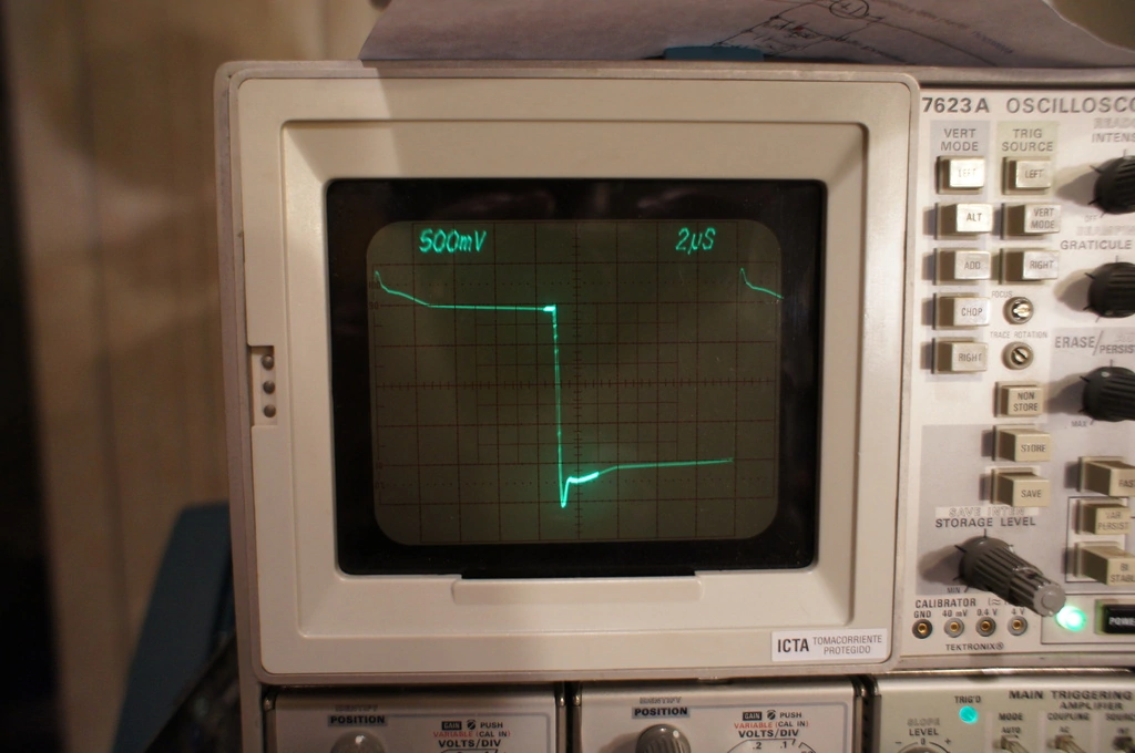 |
Here is one of the gates. There is a bit of overshoot but it's well within limits, and the gate voltage remains at about 10V after the initial switching pulse. |
 |
This shows two opposing gates at the point they switch. Driving the gate negative using a push-pull driver allows the H-bridge to have deadtime without explicitly adding it in the signal. |
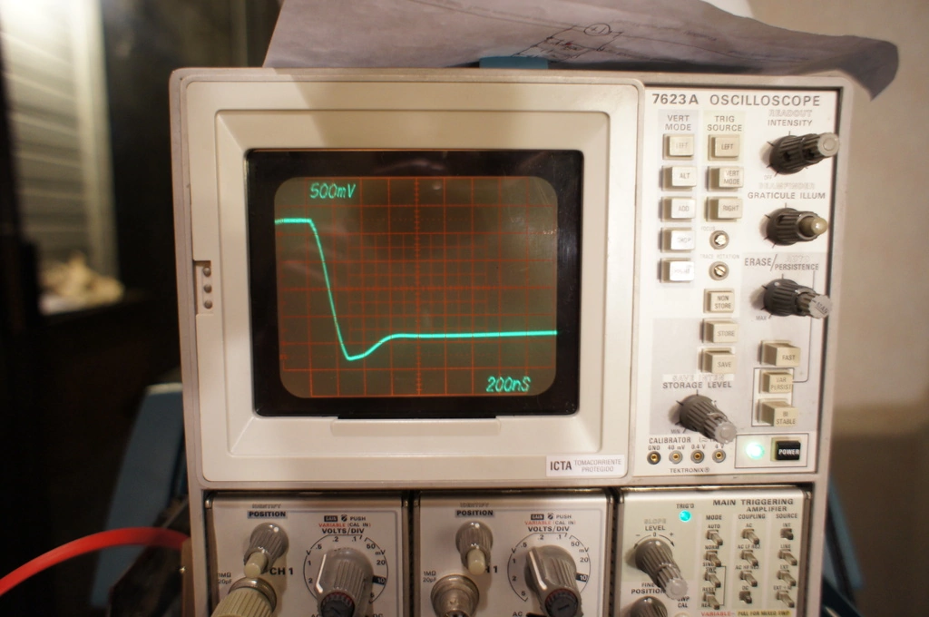 |
Here's a shot of the TVS diodes at work. Note how the gate voltage abruptly stops changing after it overshoots slightly - the TVS clamps the spike within nanoseconds. |
 |
I have no idea what caused this, but I believe it was acquired while trying to scope a gate with the probe improperly grounded. Maybe our coil is trying to show off its artistic side. |
PFC input stage
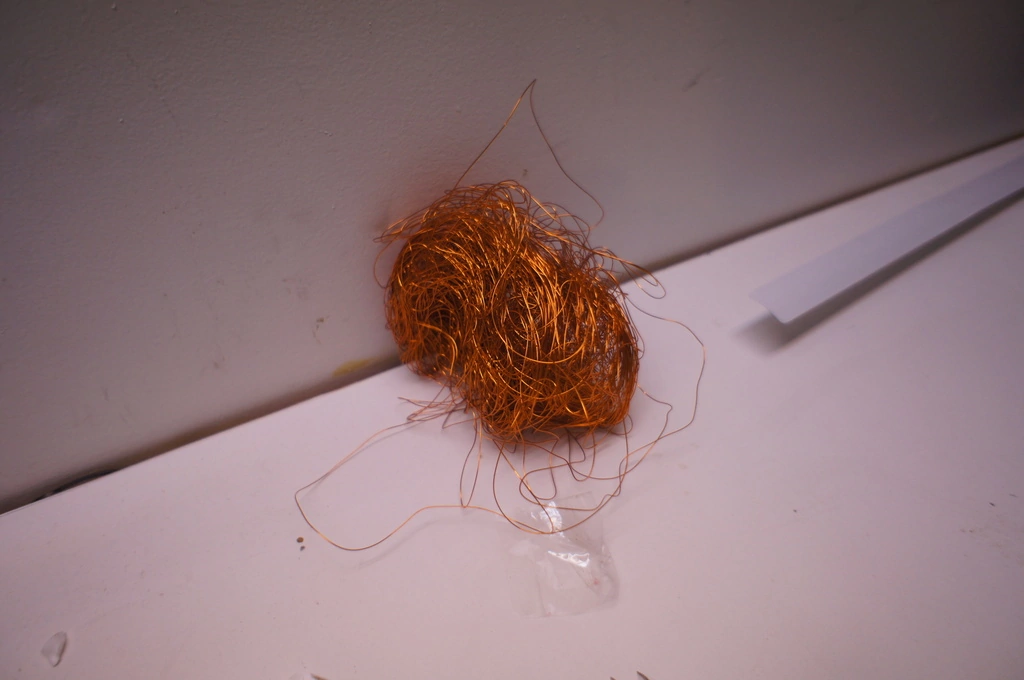
environmentally friendly coiling
For planned high-power DC operation, we needed a beefy DC power supply. Fortunately, integrated power factor correction chips are quite popular these days, and we used a UCC28019 continuous conduction mode PFC controller from Texas Instruments in our supply. These controllers sense the voltage from a fullwave rectified mains and drive a boost converter to draw current in proportion to the input voltage, generating a stable DC bus with a very high power factor (350V at 0.99 power factor on our case). This supply hasn't been used with the SSTC yet, as we still need to get the rest of the coil in shape first before feeding it with 350VDC.
Joshua has an excellent writeup of the PFC supply on his site.
PLL-based controller
baby steps
We experimented with a few different PLL circuits. The first was a CD4046-based circuit using phase detector 2, the more accurate but noise-sensitive flop-based one. Initially it was connected without feedback as just a VCO. With a pot connected to the VCO in and manually adjusted while looking at an oscilloscope trace, it was enough to achieve secondary breakout.
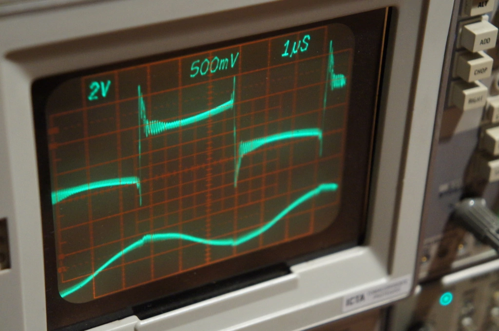 |
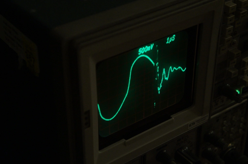
This is what the output voltage and current from the primary look like at resonance. |
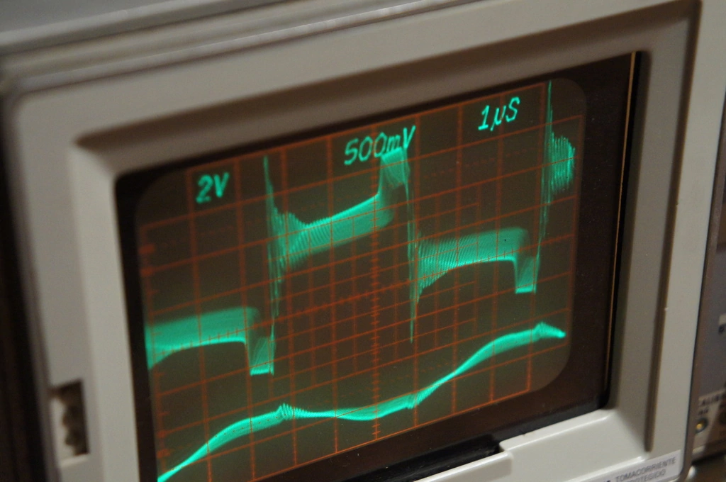 |
Too slow. Note how the voltage 'wants' to change earlier. |
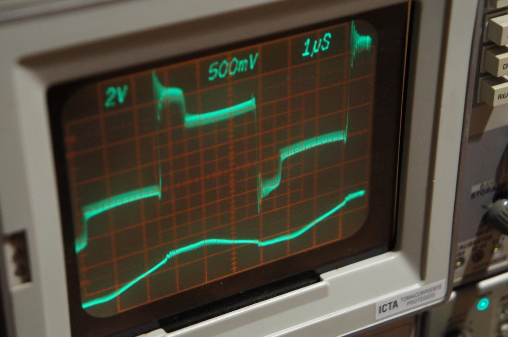 |
Too fast. |
We then added feedback in the form of an antenna, diode-clamped to the logic rails to approximate a square wave and cleaned up through 74HC14 inverting Schmitt triggers. Now we could get breakout without having to fiddle with a knob, but various delays in the system combined with the inaccuracy of the antenna feedback meant that the PLL locked to a frequency somewhat off of resonance.
once more, with feeling
The second iteration uses a 74HC9046, a newer and higher-performance version of the CD4046. We use phase comparator 2 as before, but to compensate for various delays, we added an adjustable RC + comparator delay to the signal feedback from the PLL. The frequency range of the PLL is also adjustable using two trimpots. The low-pass filter on the phase comparator output was slightly modified to give a faster response to phase differences.
badness 10000
While testing this driver we managed to violently destroy several MOSFETs while pulling arcs from the topload. This was traced to a bizarre and very annoying property of the 74HC9046: if the VCO input gets 'too close' to either rail, the VCO output frequency can deviate wildly from its set range. Normally this would not be a problem, the range is set beforehand to include the resonant frequency. However, we discovered an insurmountable issue with antenna feedback. If a ground arc is pulled from the topload, the antenna is overwhelmed by RF hash, which appears to the phase comparator as an extremely high frequency feedback signal, causing it to overcompensate and drive the VCO output to the moon. The MOSFETs do not take kindly to this sort of abuse.
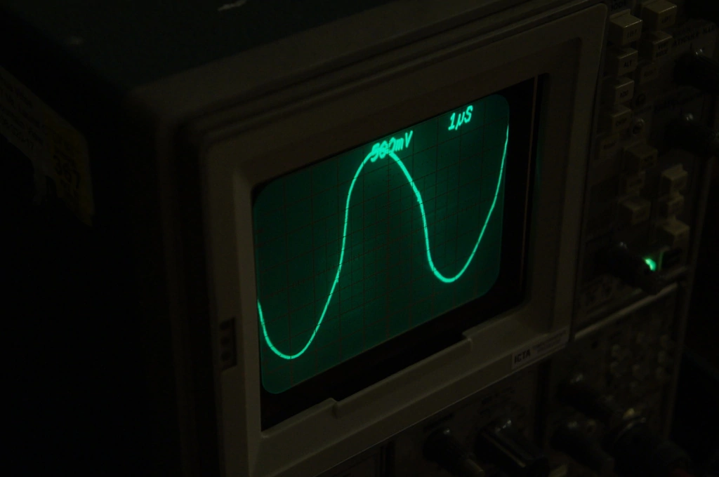 |
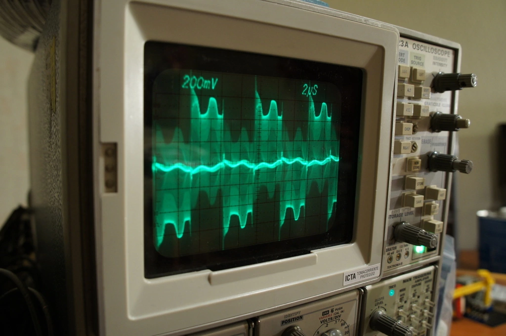
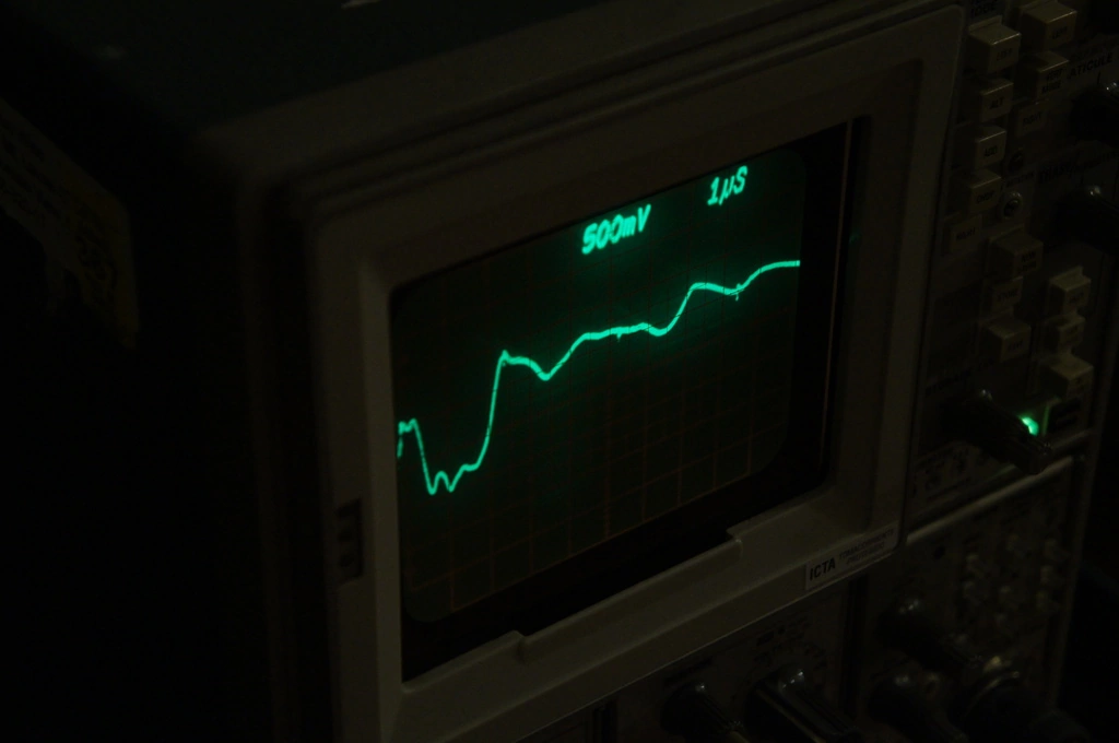
This is what the unclamped, unfiltered feedback signal from the antenna looks like. Not bad at all, we can get something out of this. |
 |
A very fortuitous scope capture of the feedback signal at the moment a ground arc strikes. There is no such thing as 'trigger on signal going bonkers', so this waveform was acquired by way of me holding a grounded screwdriver barely within arcing range and Joshua spamming the 'capture' button on the scope. After some time we caught this shot. Just as predicted, the feedback instantly spikes... |
 |
...and turns into this. Just noise. We assume this is 'cleaned up' by the filter to send a storm of edges to the phase comparator, which it interprets as 'crank the VCO all the way up'. This ends up making the MOSFETs violently eject their magic smoke. |
The controller was 'grown' bit by bit on pieces of protoboard, so there are no schematics available. I'm not particularly inclined to make them either, as it has not been made to work quite right yet.
resonator
you know you're a coiler when your electronic parts come from a hardware store
The secondary is a ~22" winding of 26AWG magnet wire on 6" PVC sewer pipe, protected by 10-15 coats of Minwax fast-drying polyurethane, enough to make the windings smooth to the touch. The primary is 10 turns of 1/4" soft copper tubing in a ~50 degree included angle cone. It is held up by six laser-cut acrylic supports, glued into slots in a 1/2" polycarbonate base plate. The secondary sits in slots cut in the primary supports.
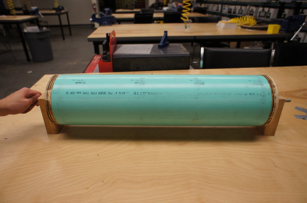 |
To wind the secondary, we made a basic winding jig with bits of 2x4, some plywood, and two bolts. |
 |
Starting the winding, always a bit tricky. |
 |
Oops. Too tricky, it seems. |
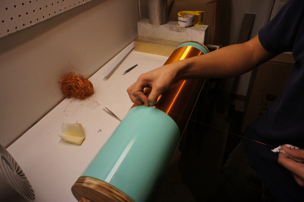 |
We have a good run going. Joshua on the drill, Jacob holding the wire spool, yours truly guiding it onto the form. |
 |
Putting the last few turns on. |
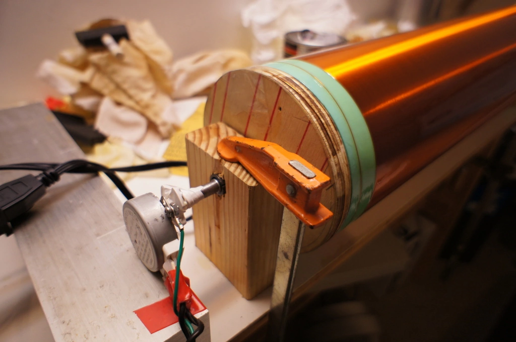 |
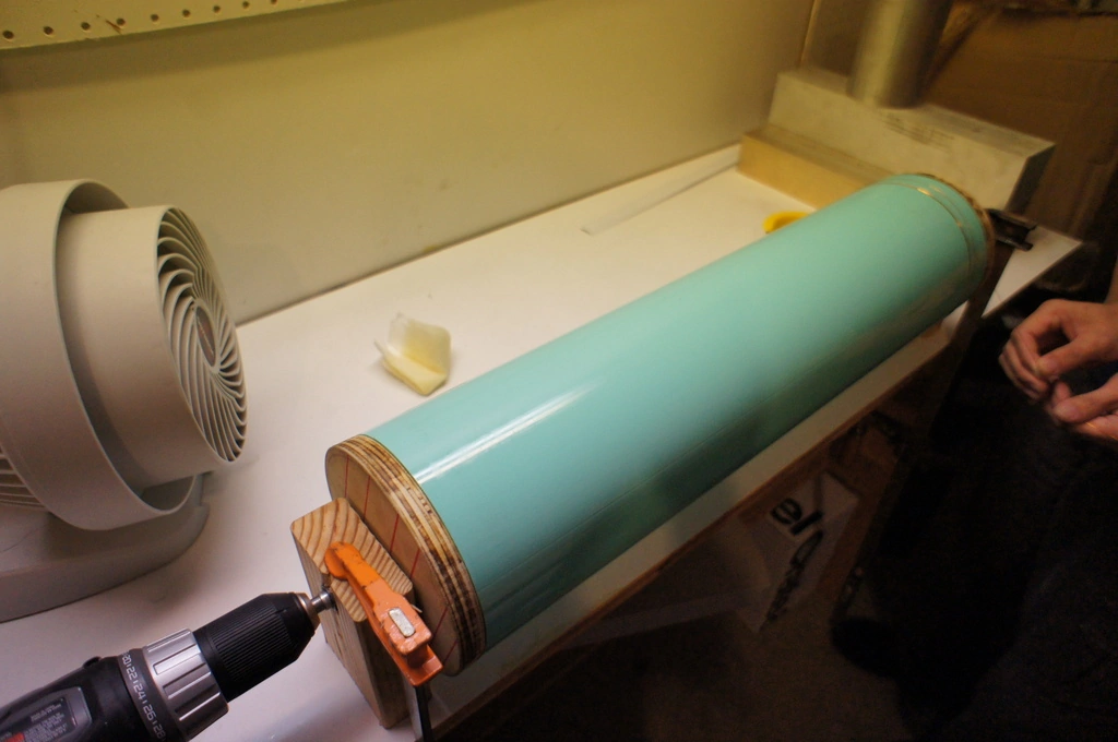
We used a microwave oven turntable motor to turn the secondary slowly after applying polyurethane, so it would dry in an even coat. |
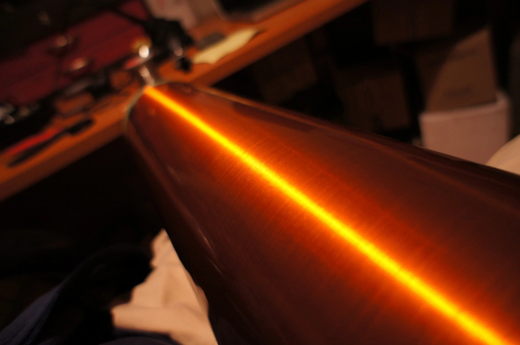 |
Close up of the windings. Mmm... |
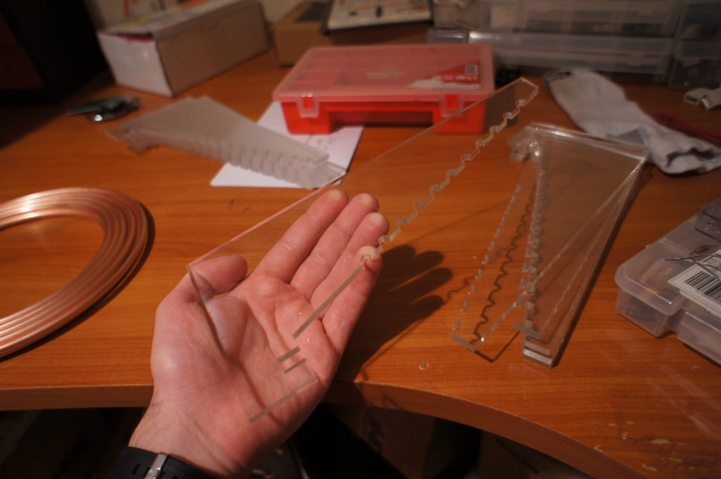 |
On to the primary, here are the supports (and some scrapped supports cut with the wrong dimensions. Oops again.) |
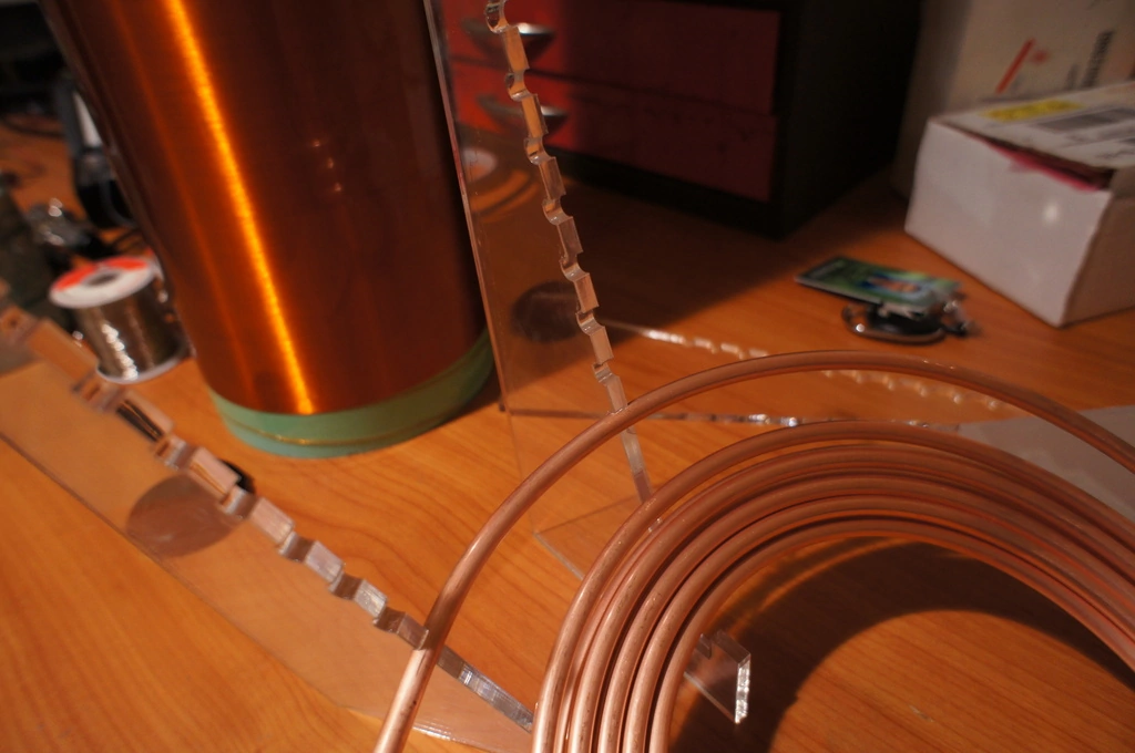 |
Test fitting some copper tube. It snaps in, just barely. |
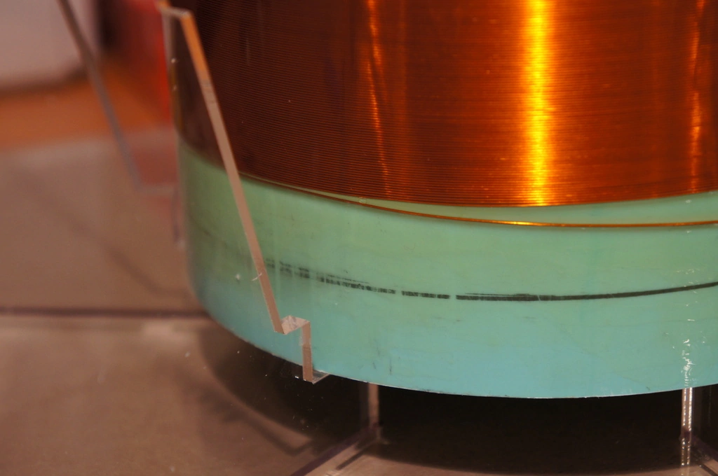 |
Close up of how the secondary fits in the slots at the base. |
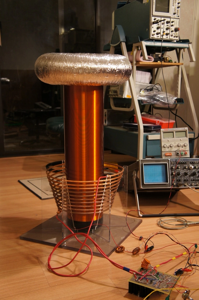 |
Assembled, with the original driver in the foreground. The topload is a piece of 4" dryer duct bent into a ring and covered in aluminum foil tape to maintain its shape. |
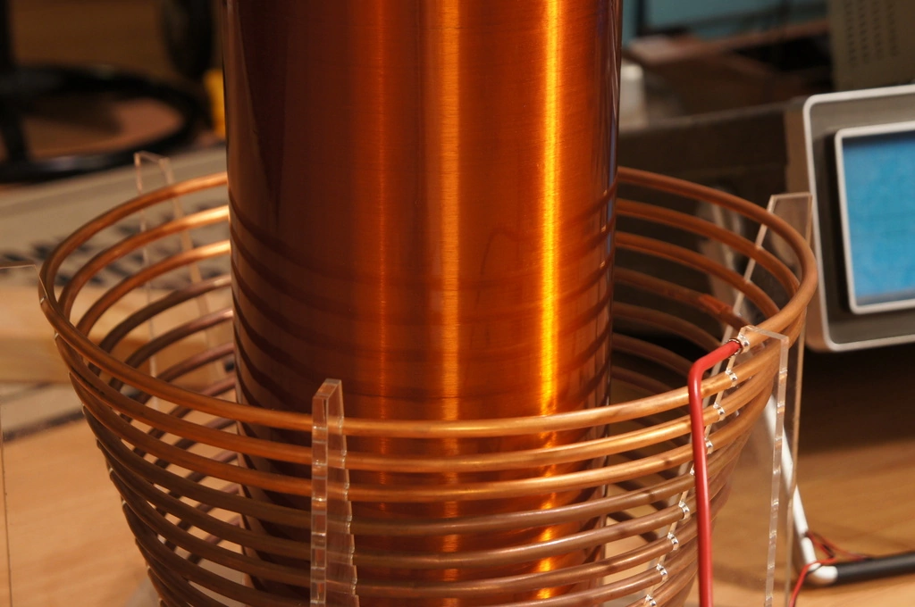 |
The primary has a bit less than 3" clearance from the secondary at the top. We found that if the strands in our 10AWG primary leads were folded back over the insulation, it would fit snugly inside the primary tube. Good enough for a test rig. |
operation
Here's the coil in action. We have not been able to turn it up to full power because the driver circuit has not been very reliable; after blowing several sets of expensive FETs we decided to keep it reasonable until the kinks are worked out.
 |
First breakout! This is running from half-wave rectified AC from a variac, at a very low setting. |
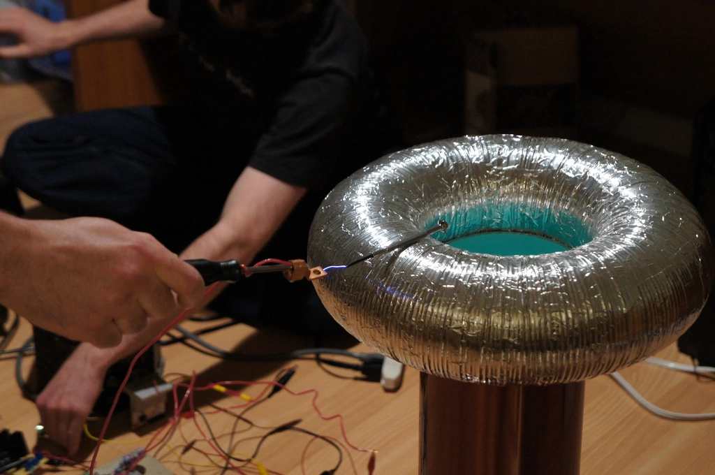 |
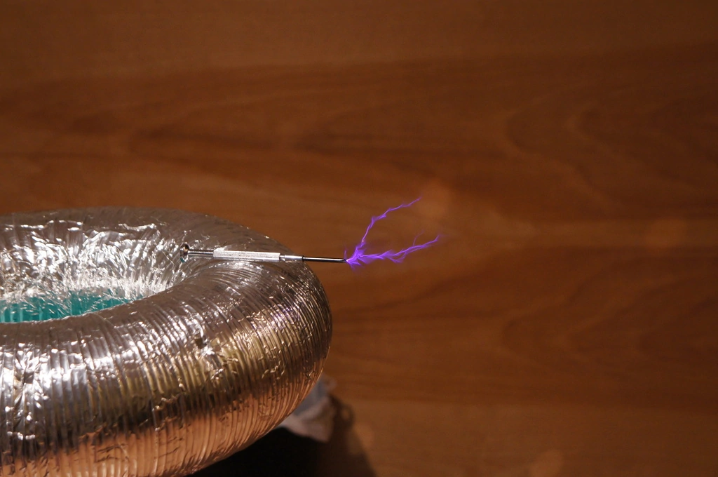
Pulling a ground arc from the top at low power. Jacob is in the background being a PLL. |
 |
Breakout from the coil at roughly half voltage on the variac. We found that the toroid got rather warm after sustained operation, so we cut a slot in it to reduce eddy currents that could be causing power loss. This didn't seem to have much of an effect. Also, note the substantial corona from the grounded screwdriver. |